How to Make an Onboard Glow Heater
Farrell Farahbod
January 24 2009
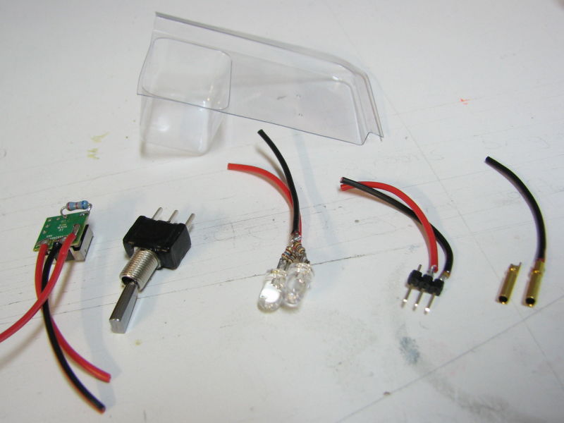
List of Materials:
- 1x Voltage Regulator: Lineage Power APXS006A0X-SRZ, $12 on Mouser.com
- 2x Blue LEDs. Lck-Led.com, Under $1
- 4x 160 ohm resistors. Under $1
- 1x Package of 2mm banana connectors. Mpi #2854, $3
- 1x Toggle Switch. $3
- Random stuff: servo connector, servo extension, epoxy, CA and blister packaging. I scavenged the glow plug connections from my Hangar9 remote glow setup.
The voltage regulator is the heart of this project. The manufacturer's spec sheet has lots of useful information, it can be downloaded at:
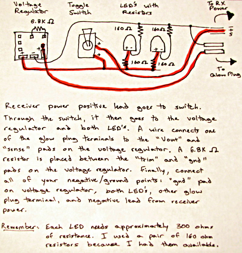
Basically we need to connect the "sense" pad to the "Vout" pad, and connect the "trim" pad and "gnd" pad with a 6.8K ohm resistor. Might as well connect your wires at this time too. I used my Vout wire to connect the sense and Vout pads ... keep things simple.
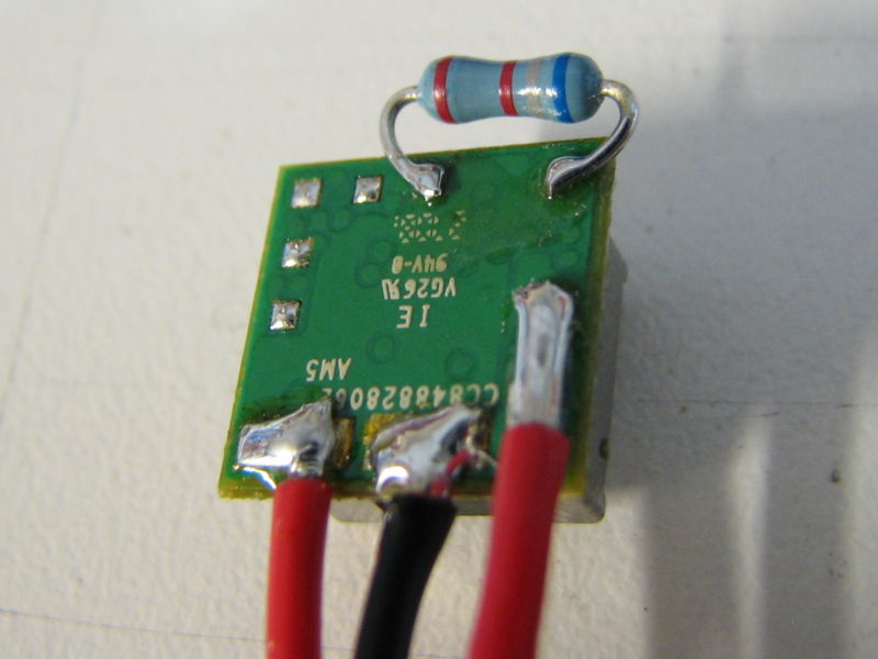
The sense pad tells the voltage regulator what voltage it sees, and since we are not doing anything complex it just needs to be connected to the Vout pad. The resistor between trim and gnd tells the regulator what voltage you want. A table of common voltages and corresponding resistors is available in the spec sheet, as well as a formula to let you pick an exact voltage. I picked a 6.8K ohm resistor because it was the closest to what we wanted, yielding ~1.3V for the glow plug.
I coated the toggle switch with some black connector coating because my first attempt at the project resulted in a failed switch when epoxy seeped in through the sides or bottom of the switch. Any glue can be used to seal up the switch as long as it has a high viscosity and does not conduct electricity.
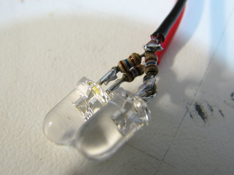
Each LED needs a ~300 ohm resistor to limit current. I had a bunch of 160 ohm resistors, so I used two of those for each LED, then wired the two LED assemblies in parallel.
To keep things compact I glued the regulator to one side of the toggle switch with a dot of Shoe Goo, then glued the pair of LEDs to the other side of the switch.
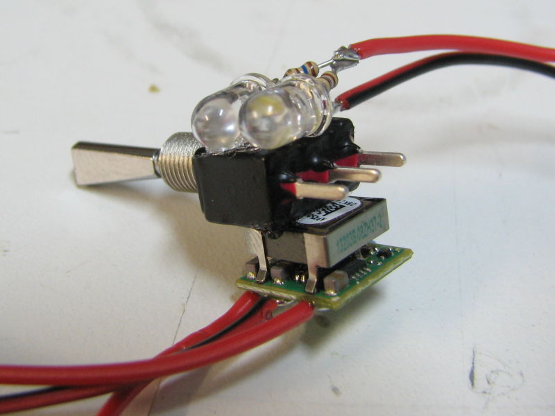
The rest is easy, you just need to connect the wires correctly, and keep it compact whenever possible. Here is a doodle showing the circuit layout... I'm not too good with schematics so bear with me.
Now cut the slot and holes in your blister package to accept the output connections. Slide your creation into the housing, slide the connections into the slot and holes, then seal the openings with a little thick CA or quick curing epoxy. If you skip this step the 30-minute epoxy will seep through. Give it all a final test to ensure it works correctly, then mix up some 30 minute epoxy and pour it in. Try not to cover up the threads of the toggle switch with epoxy, or you will not be able to securely mount it to your model.
Let the epoxy cure, then trim the excess blister packaging with a hobby knife or file. Do the trimming after the epoxy is no longer tacky. If you wait to long, the epoxy will approach a full cure and be hard as a rock.
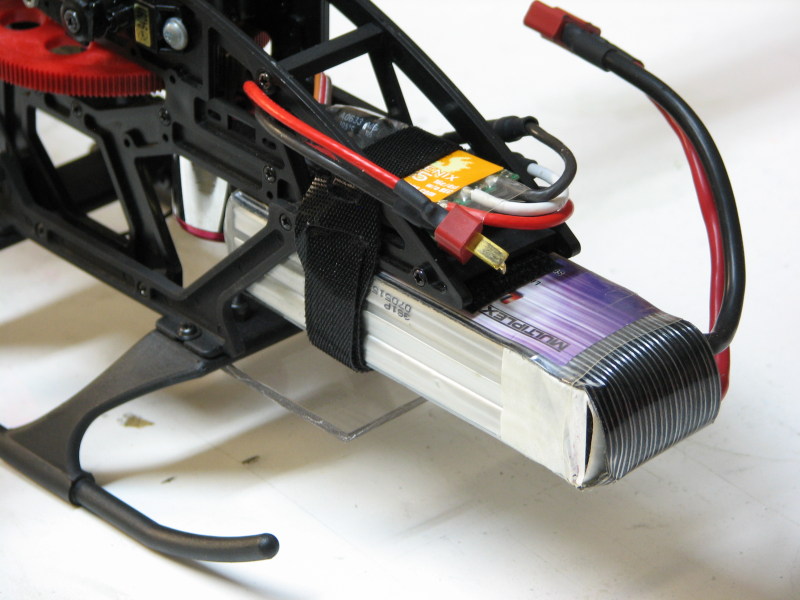
When you mount the onboard glow heater to your model, I would suggest using a little servo tape to reduce the strain on your toggle switch. Just use the toggle switch nut to keep it secure.
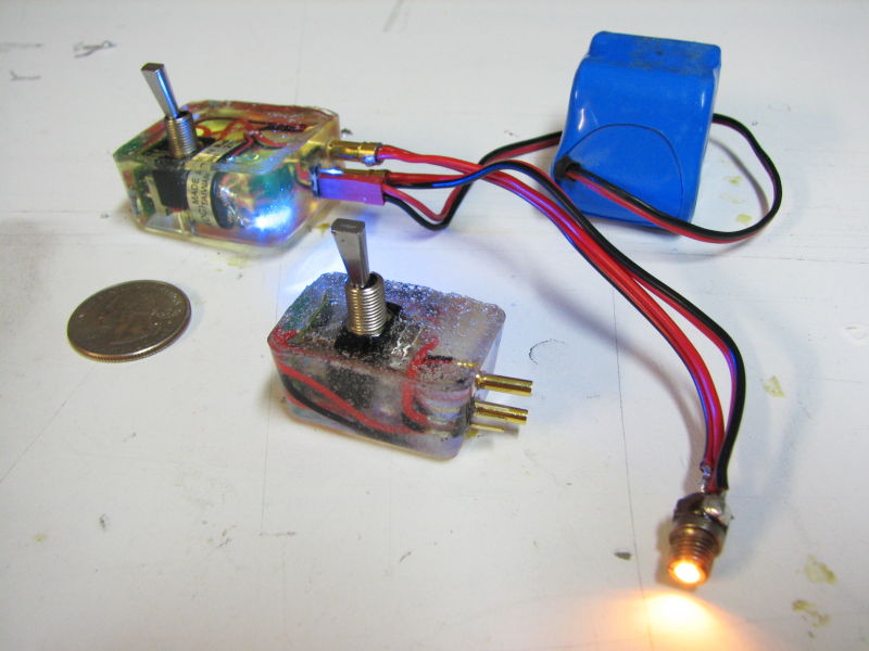
Here is the end result. An earlier version is temporarily hooked up to show the effect.
